SiC MOSFET-Based high performance double side cooled module and compact cooler for high power-density automotive inverter applications
This paper presents a high performance Double Side Cooled (DSC) module based on trench silicon carbide (SiC) MOSFETs and demonstrates the design of an optimized cooler. The cooler’s thermal performance is simulated and experimentally verified. The static and switching characteristics of the SiC module are experimentally characterized and compared against a silicon- (Si) based DSC Module to determine the benefits of SiC at the module and inverter levels.
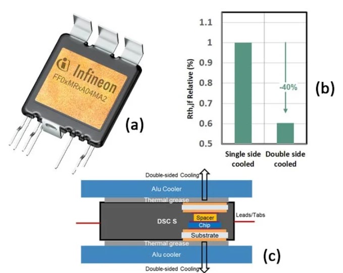
Infineon’s HybridPACK™ DSC Power Module equipped with CoolSiC™ Trench silicon carbide (SiC) MOSFETs (see Fig. 1 (a)) have been shown to offer significant benefits at the module and inverter levels [1]. Fig. 1 (b) shows that the simulated junction-fluid thermal resistance Rth,jf, of a DSC module can be reduced by 40% compared to a single side cooled module with the same footprint and under the same boundary conditions [1]. This would translate into a higher current capability, IRMS which is particularly important for semiconductors such as SiC, which are known to be materially more expensive than silicon (Si). Fig. 1 (c) shows the thermal stack of the DSC, which has been demonstrated in [1] to offer superior performance. The DSC is an indirect-cooled module and optimization of the module alone is not sufficient. It is necessary to optimize the cooler and the thermal interface material (TIM) as well. This paper presents a Eaton aluminum cooler, specially designed and optimized for the DSC module and its thermal/hydraulic simulation results are discussed. This cooler is then experimentally characterized and compared against the simulation results. Furthermore, the module is also characterized in a lab setup cooler to further understand its thermal performance. To deduce the power- loss benefits of the SiC DSC module, it is experimentally compared against a comparable Si DSC module and simulations are performed to confirm efficiency benefits at the system level.
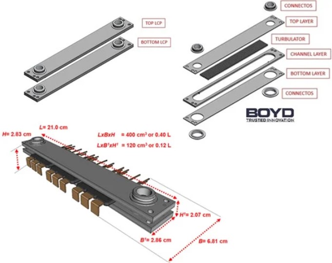
This section discusses the design of an aluminum-based application-near Eaton cooler structure for the DSC module. The cooler is kept as compact as possible, to reach a high level of power density. The double side cooling structure includes two liquid cold plates (LCP) as shown in Fig. 2 (a), along with the exploded views of the top LCP (Fig. 2 (b)). Both LCPs share the same geometry regarding number of layers, inlet/outlet connectors, channel structure, turbulator and perimeter shape. Each LCP includes a top layer with the location for the inlet/outlet hydraulic connectors, a channel layer with the location of the turbulator and a bottom layer to close the channel path. The top LCP includes two additional hydraulic connectors, in order to divide the fluid flow rate equally on both top and bottom. All interfaces between the top and bottom LCPs are sealed with O-rings. All layers are obtained by laser cut, the connectors by lathing and the turbulators by stamping. Two steel plates are added on top and bottom to compensate the bending effect during the assembling process, which might reduce the contact surface between the LCPs and the central SiC module. Fig. 2 (c) shows the cooler after integrating the DSC modules, indicating the dimensions relevant for the cooler. It can be seen that THE cooling structure combined with the module is very compact and occupies a volume of only 0.4 L as per the dimensions defined in the figure. For benchmarking the cooling performance, it would be relevant to neglect the volume of the module not in contact with the cooler and the volume in this case is 0.12 L, paving the way for a high power density. The fabricated cooler is shown in Fig. 3.
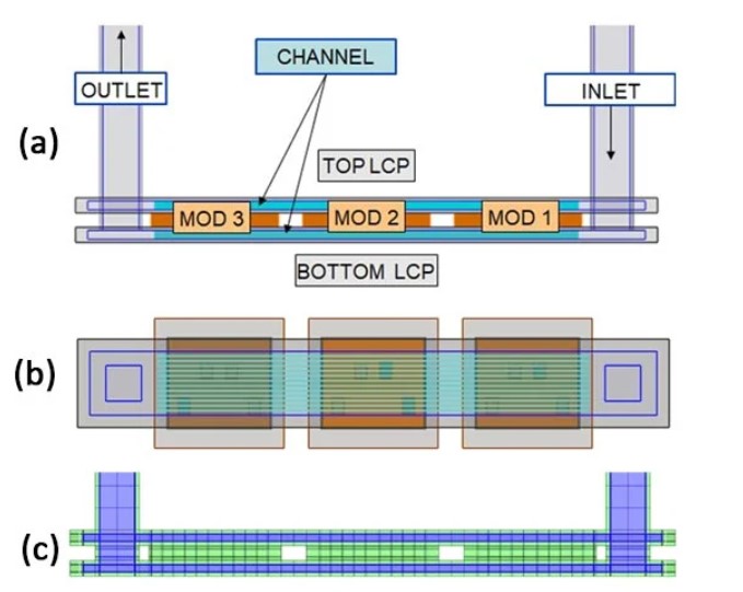
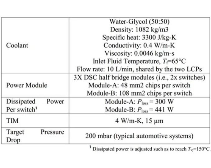
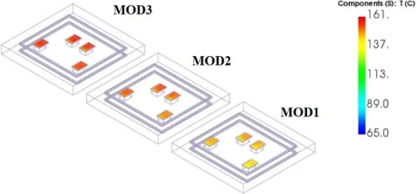
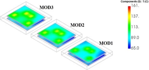
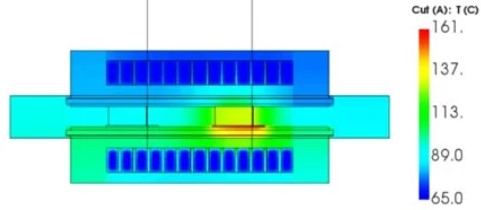
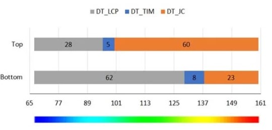
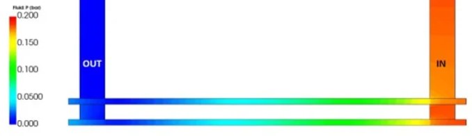
A computational fluid dynamics (CFD) simulation is run in Eaton SmartCFD to predict the thermal and hydraulic performance of the cooler. The complete internal structure of the module is implemented to calculate an accurate thermal distribution. The overview of the simulated geometry is shown in Fig. 4 and the boundary conditions are summarized in Table 1. Two modules (A and B) with different chip content are investigated. Detailed full Navier-Stokes CFD Solver is chosen for the flow-simulation considering a turbulent flow regime. Finite volume discretization is applied to represent both the solid and fluid. As the geometry is regular, particularly in the finned area, the geometry is simplified into hexahedral blocks and a hexahedral mesh is used to represent the geometry for the most accurate calculation of the behavior of fluid in contact with the cooler fins. For brevity, the metallic surfaces are assumed to be flat and the TIM has been modelled as a homogenous layer of uniform thickness between the metallic surfaces.
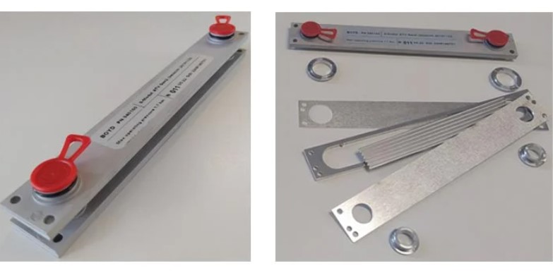
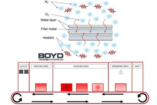
The liquid cold plates are produced by the controlled atmosphere brazing (CAB) process, a metallurgic welding process which allows the creation of a high-quality metal junction, as summarized in Fig. 7. During the assembling process, foils of filler material are located in between the aluminum layers. These foils are made of a specific aluminum mixture able to melt at a temperature of approximately 600°C. Once the assembling process is completed, the structure is clamped in a custom designed brazing jig and inserted into a pre-warmed oven area. In order to avoid oxidation, the oxygen in the chamber atmosphere is substituted with nitrogen. This step of the procedure gives the name to the CAB process. Once the oven reaches an internal temperature of approximately 600°C, the foil material starts melting, while the aluminum layers are still in a solid stage. After the cooking, the pieces proceed to the cooling areas where they are progressively brought to ambient temperature. The CAB brazing process requires a specific combination of aluminum alloy since the chemical composition of the materials is crucial to avoid micro-porosities along the brazing junction, which might cause leakage and consequently the failure of the LCPs during their operative life. For this reason, layers are made of Al3003, connectors of Al6060 and turbulators of Al1050.
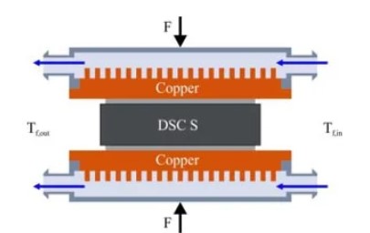
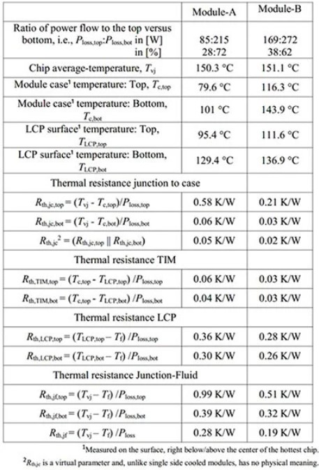
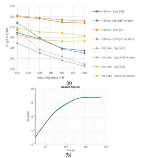
The thermal performance of the DSC module is first characterized for a lab cooler (setup shown in Fig. 8), where the modules are placed with a defined orientation between two copper heatsinks with an internal pin-fin structure that is fluid cooled on both sides. In this case only module-A will be considered. A thermal interface material (TIM)- Dowsil TC- 5021 with a thermal conductivity of 3.3 W/mK and thickness of 50 µm is applied between the module and the heatsinks. A variable clamping force F of 400 N and 1000 N is applied between the upper and lower heatsinks structure with a spring- loaded holder to ensure a preset force, independent of thermo- mechanical influences during the test, which is also continuously controlled and ensured. A water-glycol-based fluid (50:50) recirculation unit with a regulated fluid flow rate between 4-10 L/min, a controlled fluid temperature of 60 °C is used to indirectly cool the modules. This setup allows choosing between parallel or serial fluid flow configurations. Fig. 8 shows the parallel fluid flow configuration, whereby both heat sinks are supplied with the same fluid stream in parallel (50:50 ratio). For the determination of the junction temperature Tvj, the characteristic curve of the internal body diode of the SiC MOSFET is first calibrated at different temperatures. A constant calibration current corresponding to 1/1000 of the nominal current is used for this purpose. Knowing the relationship between the body diode forward voltage and Tvj, the determination of Rth can now be applied. For the case of Rth,jf measurement, a current heating pulse is applied to the ohmic drain-source channel of the DSC module until the system reaches a thermal steady-state. This pulse generates a thermal power injection, Ploss, in the semiconductor junction of the module according to Joule- heating. By means of precisely timed measurement of the junction temperature Tvj directly after switching off the current heating pulse, conclusions are drawn about Tvj in connection with Ploss. Finally by measuring Tf, Rth,jf can be determined according to the equations in Table 2.
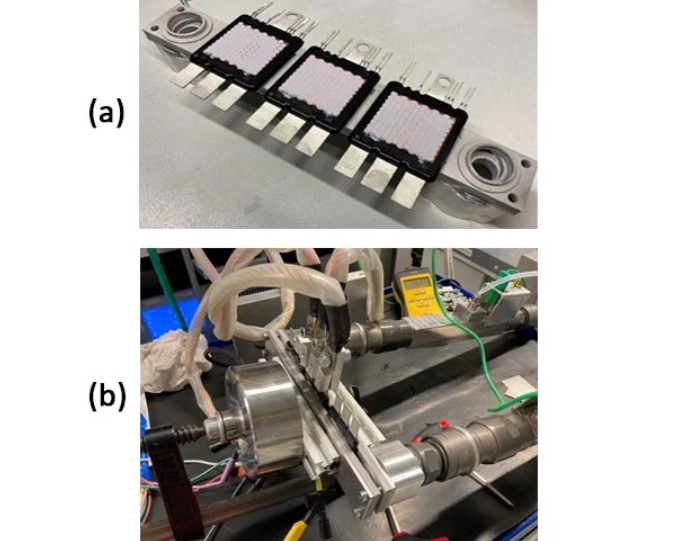
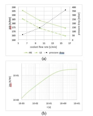
The Eaton cooler described previously is experimentally verified in the Rth measurement setup shown in the previous section (same setup and boundary conditions, except the cooler itself and the module which in this case is Module-B). TIM is first applied to the DSC modules on both sides, before mounting them on the cooler as seen in Fig. 10(a). A stencil is used to enable a uniform thickness of 50µm (before application of a clamping force). Two milled-aluminum threaded adaptors interface the cooler to the coolant circuit as shown in Fig. 10 (b). The current cooler design lacks the possibility to apply a given force from within itself (this is being implemented in an upcoming version). Therefore, a clamping structure including a force-gauge is fixed around the central area, to apply a known force (in this case 650N).
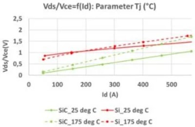
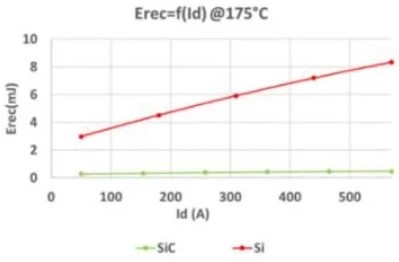
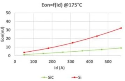
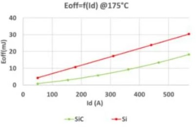
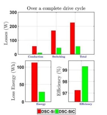
This section compares a silicon (Si) IGBT-based DSC module versus a SiC MOSFET-based DSC module. For a fair comparison [2] [3] [4] [5] [6], both modules chosen are such that they roughly cater to an RMS current of 400A at a battery voltage of 400V (details of the compared modules are in [1]). The static and switching performance of both modules are experimentally measured and compared in Fig. 12. The gate resistances for both devices are tuned to keep dv/dt <= 10 kV/µs and the voltage overshoot below the breakdown voltage, to reflect application-near conditions. It can be confirmed that the voltage drop of the MOSFET, Vds, is significantly lower than that of the IGBT, Vce, at light load due to the resistive nature of the MOSFET compared to the knee- like voltage behavior of the IGBT [2]. From the switching characteristics, it can be confirmed that the diode recovery losses Erec in the SiC MOSFET are only an eighth of that in the IGBT. This is because, minority charge carriers have a significantly lower lifetime in the SiC body diode compared to the Si FWD, resulting in a quicker extraction of charges during diode turn-off. The benefits of reverse recovery also reflect on the turn-on losses Eon, where it can be seen that the SiC module has a factor 3 lower losses than the Si module. The turn-off losses Eoff in the SiC module are lower by ~30% than the IGBT module, due to the absence of tail currents (which is again a bipolar phenomenon, relating to the decay of minority charge carriers). These measurements confirm the benefits of the SiC module. In order to check the benefits of the SiC module at the inverter level, power loss simulations are carried out for the Worldwide Harmonized Light Vehicle Test Procedure (WLTP), which is a commonly used mission profile for benchmarking automobiles [2], as shown in Fig. 13. The boundary conditions can be found in [1]. The observations in the previous paragraph can be confirmed. The conduction losses in the SiC MOSFET are lower than the Si-IGBT by >75%, whereas the corresponding reduction in the switching losses is >60%.
As a whole, the average power losses in the SiC module are 60% lower than the Si module, resulting in an improvement of the inverter efficiency by over 2 percentage points, compared to the Si module. This re-affirms the efficiency benefits of the DSC SiC module.
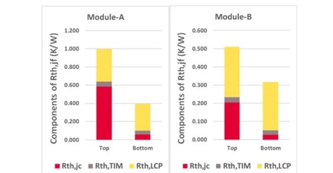
This paper presented the HybridPACK™ DSC Power Module based on CoolSiC™ Trench SiC MOSFETs, suitable for high performance automotive traction inverter applications. A compact aluminum-based cooler was designed for DSC and CFD thermal- and hydraulic simulations were performed to analyze its performance. The volume of the cooler together with the modules was calculated to only 0.4 L. It was shown that the contribution of the power module to the thermal resistance was low. The ratio of heat extraction from top to bottom was 30:70 for module- A (with 48 mm2 chips per switch), but this increased to 40:60 for module-B (with 108 mm2 chips per switch), indicating a better utilization of the thermal stack for larger chip content. Overall, the modules achieved an Rth,jf of 0.28 K/W and 0.19 K/W respectively, at 10 L/min flow. To experimentally verify the simulations, the DSC modules were characterized- module-A with a lab cooler and module-B with the Eaton cooler. As expected, the measured Rth,jf were lower than simulations due to the inaccuracies in simulating the TIM. At 10 L/min flow rate, module-A achieved Rth,jf = 0.23 K/W with the lab cooler, whereas module-B achieved Rth,jf = 0.18 K/W. For a battery voltage of 400 V, this translates into a continuous IRMS over > 450 A and power > 150 kW. This results in an impressive volumetric power density (considering just the cooler and the module) of > 375 kW/L.
Future work: work is ongoing to further optimize the cooler and to design clamping structures within the cooler to apply pre-defined force on the modules for a good contact. Also, measurements are ongoing with various TIM available in the market to determine the most suitable TIM for the DSC.
 发送电子邮件

 MyEatonFAQs


