Rack power density keeps climbing. Server racks routinely draw 10–30+ kW today, and AI and high-performance computing (HPC) designs are pushing toward 100 kW-class racks. Supplying that power means distributing hundreds of amperes — at 480 Vac into power distribution units, or across 48 V, 54 V, and 12 V DC buses inside the rack — through boards and busbars packed into tight, thermally constrained spaces.
At the same time, the cost of failure is severe: industry analyses consistently put unplanned data center outage costs in the thousands of dollars per minute. A single shorted component can escalate into a rack-level or facility-level event if the fault is not cleared quickly and locally.
Data center power designers therefore balance three priorities: maximizing electrical capacity and density, containing any single-point failure, and fitting protection into spaces with little room and less airflow. Traditional protection struggles here. Ferrule (cartridge) fuses and thermal breakers at 100+ A are physically large, require holders or bolted terminations, obstruct airflow, and run hot — impractical on modern server boards and backplanes.
The 1210HC is a family of fast-acting SMD “brick” fuses developed for exactly this environment. Named for its roughly 12 mm × 10 mm footprint, it solders to standard PCB pads and provides point-of-use overcurrent protection at currents that previously demanded holder-mounted or bolted fuses. Its interrupting capacity — also called breaking capacity, the maximum fault current a fuse can safely stop without rupturing — reaches 10 kA at 80 Vdc, meaning it can clear a 10,000-ampere fault arising from a large battery bank or capacitor array dumping into a short.
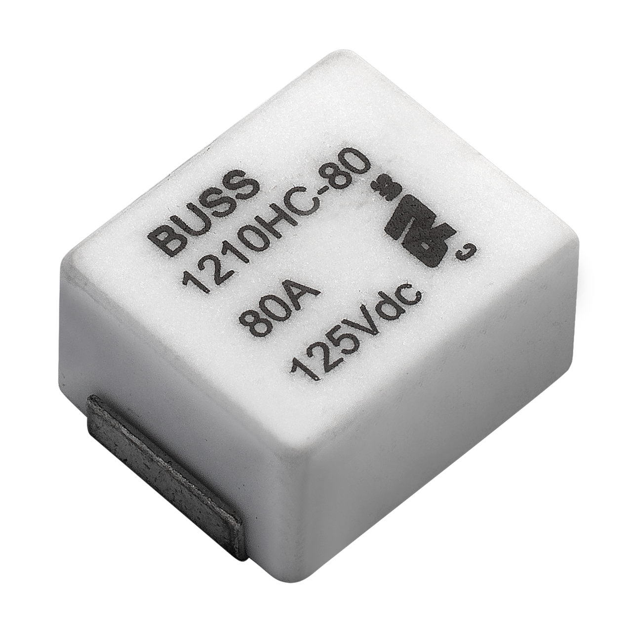 Figure 1. Eaton Bussmann series 1210HC high-current surface-mount brick fuse, 12.4 mm × 10 mm × 6.8 mm ceramic package.
| Parameter | Value | Design significance |
Current ratings |
50, 60, 70, 80, 100, 125, 150, 175, 200 A |
Single-fuse coverage of server board and branch-feed currents that previously required paralleled or holder-mounted fuses. |
Voltage rating |
125 Vdc (50–125 A models); 100 Vdc (150–200 A models) |
Covers 12 V, 48 V, 54 V, and higher DC bus architectures. DC ratings matter: DC arcs are harder to extinguish than AC. |
Breaking capacity |
Up to 10 kA at 80 Vdc (UL); 6 kA at 100 Vdc / 3 kA at 125 Vdc (50–125 A); 10 kA at 75 Vdc (TÜV, 150–200 A) |
Safely clears multi-kiloampere faults — sized for prospective fault currents on 48 V and 54 V distribution fed by batteries or bulk supplies. |
Typical cold resistance |
0.24 mΩ (200 A) to 1.02 mΩ (50 A) |
Sub-milliohm resistance keeps I²R loss and heat negligible at hundreds of amps; typical voltage drop 70–79 mV at rated current. |
Opening time |
4 h minimum at 1.0× rating; 10 s maximum at 2.5× rating |
Fast-acting characteristic — clears short circuits in milliseconds, limiting let-through energy to downstream semiconductors. |
Pre-melting I²t |
925 A²s (50 A) to 40,000 A²s (200 A) |
I²t (let-through energy) is the energy needed to melt the element — the key figure for checking the fuse survives inrush surges. |
| Package | 12.4 × 10.0 × 6.8 mm, surface-mount; MSL 1 |
Reflow-solders to a standard land pattern; no holder, no hand assembly. Tape-and-reel, 500 pieces per reel. |
Operating temperature |
−40 °C to +105 °C with correction factor applied |
Covers server chassis internals; apply the datasheet derating curve at elevated ambient. |
Agency approvals |
UL Recognized to UL 248-1 & 248-13 (file E56412); TÜV to IEC 60269-1 & -7; RoHS, halogen-free |
Simplifies end-product safety compliance in global markets. |
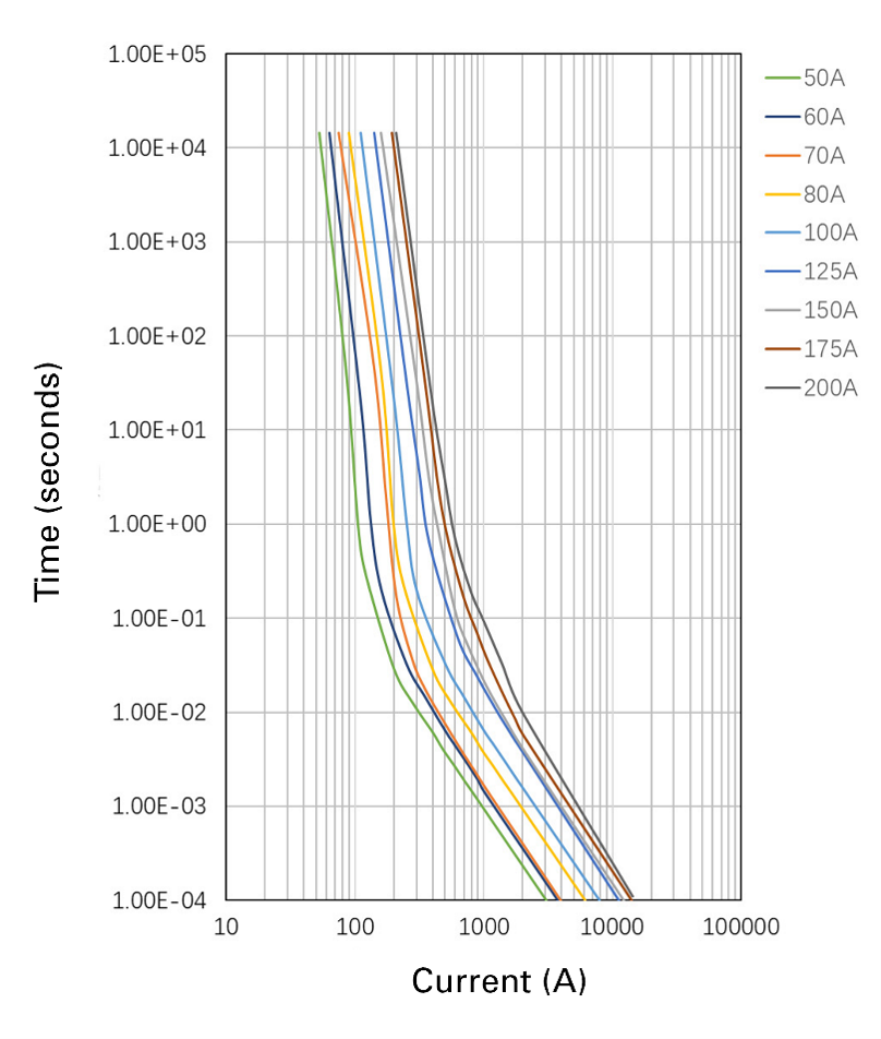 Figure 2. 1210HC time–current characteristic curves: opening time (seconds) vs. current (A) for each rating, from datasheet ELX1447. Engineers select fuses from this curve.
Server backplane protection
Server backplanes distribute a main DC bus — typically 12 V, 48 V, or 54 V at up to hundreds of amps — from bulk power supplies to a dozen or more blades or drive bays. Protecting that bus traditionally meant cartridge fuses or breakers at the input, off-board or in bulky holders.
Consider a backplane that used two paralleled 60 A axial fuses per rail to share a ~120 A load. Replacing the pair with a single 1210HC 125 A fuse eliminates the fuse clips and their required clearance, returning board area to connectors and signal routing; the low-profile package can also clear the way for taller heat sinks on nearby converters. In normal operation the fuse’s sub-milliohm resistance is electrically invisible. When a blade shorts the bus, only that backplane’s fuse opens — the fault is confined to one chassis and the rest of the rack sees no disturbance.
An SMD fuse is not field-replaceable by itself, but this matches modern service practice: the backplane is swapped as a module, while dual-feed architectures carry the load on the redundant path in the meantime.
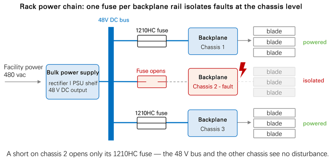 Figure 3. Fuse placement in the rack power chain: one fuse per backplane rail isolates faults at the chassis level.
Rack PDUs take facility power and distribute it to individual feeds — increasingly as 48 V DC (the OCP/Meta and Microsoft rack standard) or 54 V DC (the NVIDIA rack standard) in telecom and hyperscale designs. A PDU board serving several 100 A branch feeds can protect each branch with one 1210HC (100 A or 125 A rated) instead of knife-blade fuses or breaker modules, fitting more fused channels into the same form factor with no moving parts to maintain.
Because the fuses sit on a PCB, current sensors and telemetry can sit next to them, giving per-branch monitoring and fuse status in a compact protection scheme. The series’ breaking capacity is specified to meet server PDU interrupting requirements: 10 kA at 80 Vdc comfortably covers prospective fault currents on both 48 V and 54 V distribution.
Six factors govern selection. Applied together, they prevent both nuisance opening and unprotected faults.
1. Continuous current — the 80% rule
Never run a fuse at its rated current continuously. Limit steady-state load to about 80% of the nominal rating: an 80 A rail calls for a 100 A fuse. This keeps the element cool and prevents fatigue from load variation.
2. Temperature derating
Fuses carry less current at elevated ambient. Server chassis interiors run well above ±25 °C, so apply the datasheet derating curve on top of the 80% rule when sizing for boards near hot components or in restricted airflow.
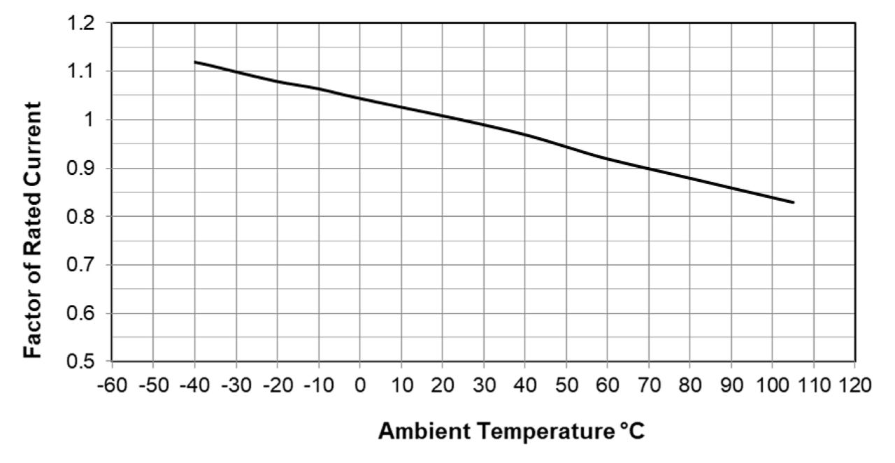 Figure 4. 1210HC temperature derating curve: derating factor vs. ambient temperature, −40 to +105 °C.
3. Interrupting rating vs. prospective fault current
The breaking capacity must be at least the worst-case fault current the source can deliver. If a busbar can push 5 kA into a short, the fuse needs ≥5 kA capacity at that voltage. Never assume a fuse will clear a fault beyond its rating — the result is rupture or sustained arcing. Where a large battery bank exceeds the fuse’s limit, choose a different fuse or add current limiting.
4. I²t coordination with inrush
Fast-acting fuses protect semiconductors well but can open on power-on surges if not checked. Calculate the I²t of the worst inrush event (for example, a brief 300 A capacitor-charging surge) and confirm the fuse’s pre-melting I²t exceeds it with margin. The 1210HC family spans 925 A²s to 40,000 A²s, so moving up one rating usually resolves a marginal case.
5. Voltage rating
The fuse’s voltage rating must meet or exceed the maximum circuit voltage including transients. This is stricter in DC systems because a DC arc has no zero-crossing to help extinguish it — a fuse operated above its DC rating may fail to clear and sustain an arc. The 1210HC’s 125 Vdc rating (100 Vdc for 150–200 A models) covers 12 V, 48 V, 54 V, and 72 V architectures with margin — spanning both the 48 V rack standard (OCP, Meta, Microsoft) and the 54 V rack standard (NVIDIA).
6. Thermal and mechanical integration
The fuse dissipates heat into the board — roughly 7–16 W at full rated current across the family (typical drop 70–79 mV) — so provide adequate copper. Eaton recommends minimum trace cross-sections of 5 mm² up to 70 A, 7 mm² for 80–125 A, and 17 mm² for 150 A and above, plus the published land pattern and sound reflow practice: a poor solder joint adds resistance and blocks the heat path. Finally, confirm agency requirements for your market; UL 248 recognition and IEC 60269 conformity cover most equipment standards, but applications such as telecom NEBS may add constraints.
Use a single properly rated fuse whenever possible. The 1210HC fuse was specifically developed to eliminate the need for paralleling multiple fuses to achieve current ratings in the 100 A to 200 A range. However, if future system requirements exceed 200 A on a single power feed and dividing the circuit is not a practical option, fuse paralleling can be a viable solution, provided that five key guidelines are carefully followed.
Use identical fuses only. Same model, same rating, ideally the same production lot. Never mix ratings: the lower-resistance fuse takes disproportionate current and blows first. Identical fuses in similar conditions typically share within 5–10%.
Mount for balance. Place the fuses adjacent, in the same orientation, tied to the same input and output copper planes, so current divides by element resistance rather than by trace asymmetry, and both see the same cooling.
Derate the pair. Two fuses do not carry twice the current of one. Treat the combination as roughly 1.6–1.8× a single fuse to absorb tolerance and imbalance — additionally, apply the standard 80% derating factor (1.25x safety factor) convention for typical fuse sizing. Worked example: two 150 A fuses sum to 300 A but electrically function like a 255 A fuse after accounting for tolerance and imbalance using a 1.7x multiplier. Applying the 80% derating factor to the 255 A combined rating nets 204 A which is the max recommended continuous current for this parallel fuse combination.
Each fuse must interrupt the full fault current alone. In a fault, one fuse always clears first, leaving its partner to carry and interrupt the entire fault. If the prospective short-circuit current is 8 kA, each fuse individually needs a ≥8 kA interrupting rating — paralleling does not add interrupting capacity, and relying on shared fault current is dangerous.
Expect sequential blowing — paralleling is capacity, not redundancy. Under serious overload both fuses open in quick succession; the circuit ends up open either way. In a marginal overload one fuse may open first and leave the other stressed, so ensure any sustained overload sits far enough above one fuse’s rating that both clear together and the feed is removed cleanly.
In short: rate the pair conservatively, verify equal temperatures under real load, and treat treat two 150 A fuses as a ~190 A-215 A solution, never 300 A.
Selective coordination means the protective device nearest the fault opens first, and only that device. A fault on one server board should blow that board’s fuse — not trip the rack PDU breaker; a rack-level fault should trip the PDU breaker — not take down the data hall. Fast-acting board-level fuses make this hierarchy work by clearing faults in milliseconds, before upstream devices respond.
The same speed underwrites redundancy. Dual-corded servers fuse each input feed; when one feed faults, its fuse opens fast enough that the redundant feed carries the load without disturbance. Isolating faults at the lowest level of the power hierarchy, and preventing cascades, is how board-level protection contributes to five-nines availability. As rack currents keep rising, fuse technology and system design will continue to evolve together — and compact, high-interrupting-capacity SMD fuses like the 1210HC are the current answer to protecting more power in less space.
 发送电子邮件

 MyEatonFAQs


